
Guide to…Mini Retro-Pi Setup
I’ve played around with Retro-Pi in the past, using a fairly standard setup (screen, keyboard and USB game-controllers). This created quite a nice setup using the re-purposed portable DVD screen, but it is only really semi-portable (not really pocket-able).

What I really would like is a little portable setup, which can be used as a tiny game system (and as a mini programming/hacking setup).
I have several Raspberry Pi setups with built-in screens. I even have some Li-ion battery packs and USB chargers. Of course, I also have little the DIY game-pad kit I produce*.

* although I don’t actively sell them at the moment (as I felt I couldn’t guarantee swift shipping and service). However, I do have a few left in stock so email me from the address on the contact page and I’ll do my best to get back to you.
Although these form the components of a potential mini Retro-Pi setup, without a custom built case it wouldn’t be particularly practical one. Therefore, I really needed something to try out before creating a more embedded version so I can work out what features I’d want and ensure it works together nicely.
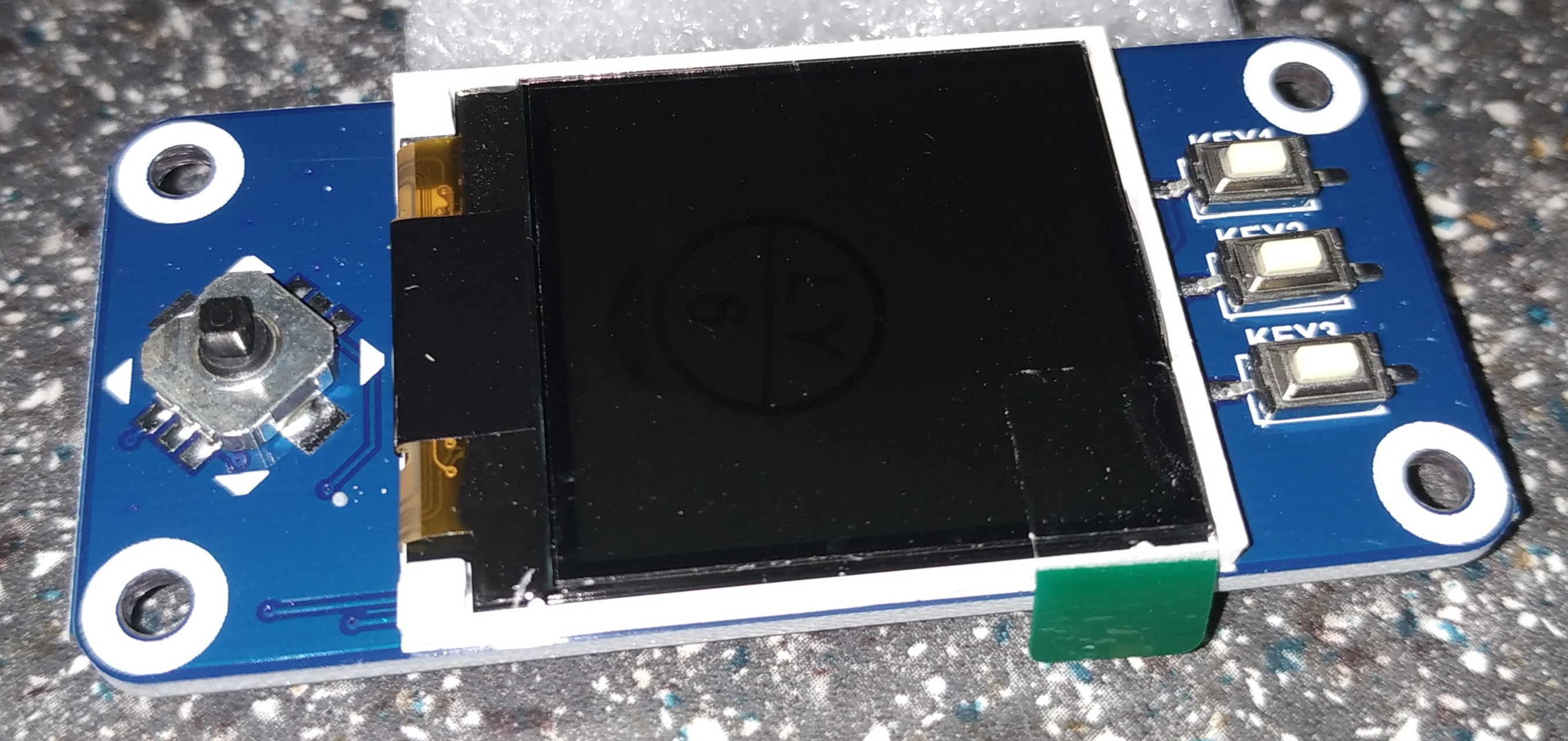
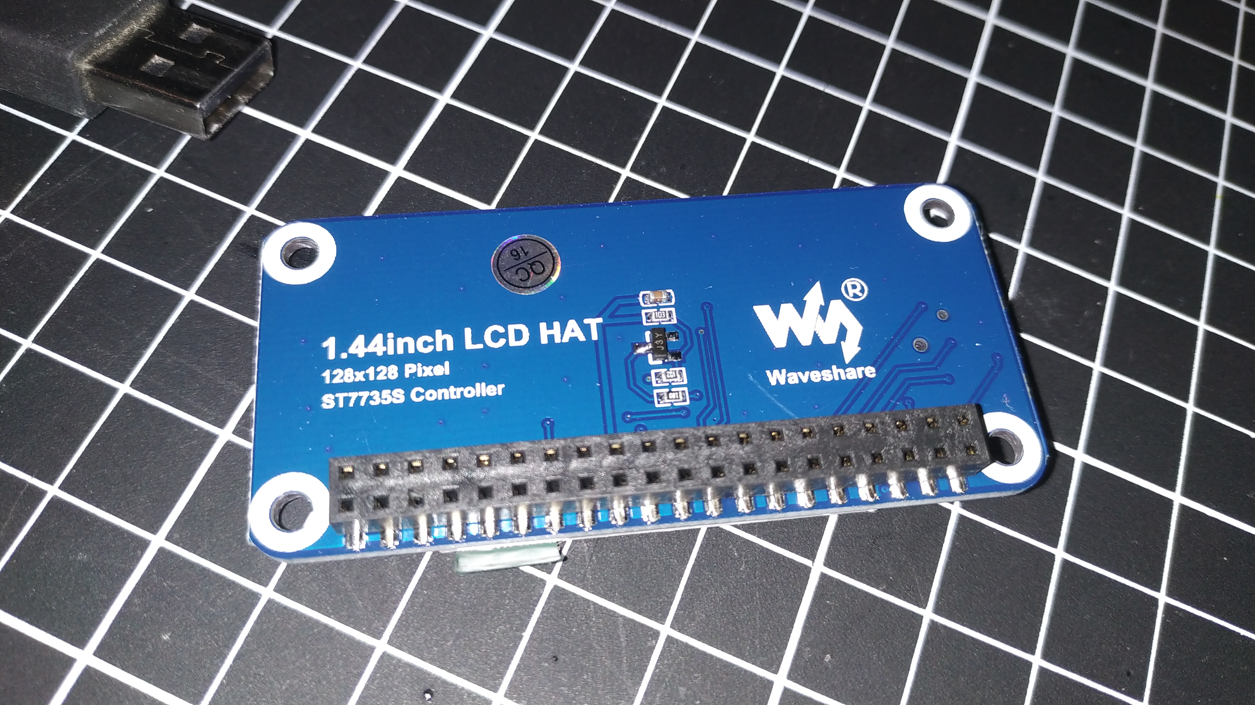
Then I saw this little board, which provides a little screen (120×120 1.4″) and some buttons, in a nice little form-factor which would stack directly onto a Pi Zero. I figured this would allow a neat setup which would allow testing of various setups and also something I could use as a user interface for many other Raspberry Pi based projects.
My aim will be to script all the setup so I can use Ansible roles to build a Retro-Pi setup and/or add screen support into any existing Raspberry Pi.
Getting started – A False Start
Initially I started my attempt using the details from the following thread:
Raspberry Pi Forum – waveshare 1.44″ tft lcd HAT (st7735s) (Solved) – greenlantern23
I started with a completely new Full Raspbian image, taking note of the steps so I could script them later. However…cutting a long story short, I couldn’t get the screen working… I figured rather than chase round in circles I’d move onto plan B (I can always come back to this once I have a reference system up and running).
Plan B
Within the thread and elsewhere others had reported success using a pre-built Retro-Pi image with a few adjustments. Although not my favourite way to do things (I like to understand it and be able to reproduce it from scratch), at least I could confirm the screen worked and have a working configuration to work from.
The good news it worked!

I downloaded the Retropie image from Pi0Pocket – TinyPi-Retropie-v4.3.zip and wrote the image to the SDCard using Win32DiskImager.
The configurations I used were as follows:
/boot/config.txt (comments removed for brevity)
disable_overscan=1
dtparam=spi=on
# Enable audio (loads snd_bcm2835)
dtparam=audio=on
gpu_mem_256=128
gpu_mem_512=256
gpu_mem_1024=256
#overscan_scale=1
dtoverlay=pwm-2chan,pin=18,func=2,pin2=13,func2=4
hdmi_force_hotplug=1
hdmi_cvt=128 128 60 1 0 0 0
hdmi_group=2
hdmi_mode=1
hdmi_mode=87
display_rotate=1
#disable uart to boost boot speed
enable_uart=0
/boot/retrogame.cfg
LEFT 5 # Joypad left
RIGHT 26 # Joypad right
UP 6 # Joypad up
DOWN 19 # Joypad down
LEFTCTRL 13 # 'A' button JOY PRESS
LEFTALT 16 # 'B' button BTN3
Z 20 # 'X' button BTN2
X 21 # 'Y' button BTN1
ESC 13 16 # Exit ROM JOY + BTN3
/etc. …
WiFi Settings
As normal, you can place a wpa_supplicant file in the root of the SDCard to be copied over when it starts up.
Ensure you at least use the following command to at least obscure your password (if copied this hash will still work on other devices so it isn’t much of a security measure, but it at least makes it less memorable).
wpa_passphrase SSID PASSWORD
network={
         ssid="SSID"
         #psk="PASSWORD"
         psk=c21xxxxxxxxxxxxxxxxxxxxxxxxxxxxxxxxxxxxxxxxxxxxa333
 }
Paste the resulting psk into your /etc/wpa_supplicant/ wpa_supplicant.conf file (without the #psk comment of course).
I highly recommend putting an extra SSID entry in your wpa_supplicant file which you can remember easily. That way you can always start a WiFi Hotspot on your phone, with those settings, and access the device using a SSH terminal app, like JuiceSSH.
Note: If your phone doesn’t display the IP it allocates to devices that connect to it’s WiFi Hotspot – which is rather frustrating!
You can either try connecting using the hostname, or lookup the IP address via the RetroPie menu.
SSH & Samba Share
If you use SSH and intend on connecting the RetroPie to your network, then make sure you change the default password and enable SSH (you can do this via the raspi-config options).
I also highly recommend enabling SMB (network share) via the RetroPie Setup.
Run the RetroPie setup with the following command:
cd ~/RetroPie-Setup; sudo sh retropie-setup.sh
Under Configuration / tools select samba – Configure Samba ROM Shares. This will make adding/removing ROMs and changing settings that much easier when connected to your network.
ROMs
Note: Retropie does not come with game ROMs (for legal reasons). You will need to obtain your own ROMs to use an the systems you install. Sources of ROMs will not be discussed here.
By default, without ROMs installed only the RetroPie Configuration page will be visible, however once you add suitable files into ~/RetroPie/roms/, pages for each game system will appear.
If you configure the SMB share above, it is very easy to drop new ROMs (that you own) onto the network share from a Windows machine.
It is important to remember that this add-on only provides 3 buttons (plus joystick central press), so it isn’t going to be suitable for all types of game systems. For now I’ve stuck to a small selection of Gameboy and MegaDrive/Genesis ROMs I used to play.
Later on we could add some additional buttons (particularly if we put it in a case of some kind), for Start and Select etc.
Power Control Button
As always, it is important that the Raspberry Pi is shutdown correctly before it is powered off. That can often be difficult if you haven’t got a keyboard connected or you can’t easily navigate to the RetroPie menus.
Fortunately the software supports the ability to allocate a GPIO pin as a “soft” shutdown button. While this doesn’t fully power off the device it will trigger a software shutdown (allowing safe removal of the power). By default this is set to gpio_pin 3 (that is BCM GPIO 3 and the physical pin BOARD GPIO 5). Pin 5 is rather useful since it has a hardware pull up it can be shorted directly to Ground safely (as it has a resistor already on the board, limiting any current and not causing a short circuit). Pin 5 is also hardwired to trigger a reset from sleep.
In another words, you can connect a simple push button between Pin 5 (BCM GPIO 3) and Ground (i.e. Pin 6). This will not only trigger a shutdown when powered on, but will also cause the Raspberry Pi to power up again if previously in sleep mode. Giving us a combined Sleep and Power up button.

To enable, add the following lines to /boot/config.txt:
#Enable shutdown button
dtoverlay=gpio-shutdown,gpio_pin=3
#Enable poweroff on BCM24
#dtoverlay=gpio-poweroff,gpiopin=24,active_low="y"
Now it works, I can wire in a proper button and mount it as part of the case.
Controlling the Screen
The 1.44″ LCD button module has the following pin configuration:

1.44 inch LCD Screen and Button schematic
From the above able we can see that the backlight is controlled by BCM Pin 24 (which is physical pin 18).
Therefore we can use the following script to toggle the screen on and off. At the moment this isn’t too useful, but if we add more hardware buttons we can use this to switch the screen off when we aren’t using it (helpful if we are using the Raspberry Pi remotely via a network connection).
Power
Unless you are happy being tethered to the wall by a USB cable, portable power is a must. Thankfully most portable phone chargers can be used (at least with the lower end Raspberry Pi Zero etc.). Alternatively there are some Li-ion power boards available too, which are more likely to supply enough current for newer Raspberry Pi versions.
Ultimately, I might dismantle a cheap USB power pack and use that as part of the build, to make a little PiZero setup.
Summary
The waveshare 1.44″ hat provides an excellent little gaming device, but it does require a little fiddling around with to get setup. As a little Gameboy emulator it is ideal, with the added bonus you can remotely connect and do some programming on the side. The little screen and buttons mean only the most basic games will make sense on it, but it is versatile enough that it can be used in many other projects too.
