
Guide to…Breadboarding
What is a Breadboard?
In order to make circuits and try them out you will need to be able to connect components (functional bits) together. There are lots of ways to do this, however a good hobbyist solution is to use something called a breadboard.

- Prototype of H-Bridge Motor Controller on a Breadboard (as featured in MagPi Issue 8)

![]() Breadboards are ideal for prototyping and performing electronic experiments. They provide a quick and easy way to wire up and test without the need for soldering by allowing you to simply insert component wires into the holes.
Breadboards are ideal for prototyping and performing electronic experiments. They provide a quick and easy way to wire up and test without the need for soldering by allowing you to simply insert component wires into the holes.
Often it is useful to test a circuit design by quickly laying it out on a breadboard, making a few measurements and perhaps even swap a few components around and observe the results.
All Laid Out
A breadboard is made up of a grid of holes which each contain a metal connector inside, allowing wires and component pins to be easily inserted and held in place. While the size and layouts of breadboards vary slightly depending on the manufacturer, most will follow several basic conventions.
- The board will have a middle section, split into two or more blocks (with a gap between them), within these blocks the pins are connected together vertically (so each hole in each column is connected to the one above or below, but not the one to the left or right, or to the block above or below).
- The board will have a few rows along the top and bottom, these are connected horizontally, and are often used to provide “power rails”. Some boards also have more than two, which allow you to use them as bus lines (common links for data and communication between circuit sections). On larger boards, these may also be separated into sub sections along the board (so be sure to test to see if the rails extend along the whole board or not – you can add temporary wire links between them if you need to).
- The gap between the middle blocks are designed for DIP (dual in-line package) ICs (integrated circuits), allowing for all the pins to be inserted into the board without connecting any of them together. The IC is placed lengthways on the board, with its centre over the middle and one side in each block. You can protect the pins when inserting and removing the IC, by using an IC chip holder as shown. Having an extra small breadboard just for ICs is quite handy and is worth getting in addition to a larger breadboard.

- Top and bottom rows are connected horizontally. The middle blocks are connected vertically.

Making Connections
Once you insert components into your “breadboard”, you will also need to complete the circuit by connecting up the different sections of the board. You can buy precut wires with suitable ends for pushing into breadboard, or alternatively some single solid-core (i.e. not multi-stranded) wire (0.6mm or 22 gauge – a common size) works just as well. As you progress to more complex circuits, you will find it helpful to use different coloured wires to signify signals, ground and supply wires, so having a selection available is a good idea.

- Single Core Wire is ideal for connections

Helpful kit
A bad workman blames his tools, a very bad one, has none to blame!In order to get started with electronics it is very helpful to gather up a few tools to use, fortunately this does not need to be costly and you can gradually build up your collection over time.
Depending on if you intend to use pre-cut wires or solid core wire off a reel, you may need some tools for cutting, bending and “stripping” (removing the outer plastic) wires. A few small hobby tools, such as pin-nose pilers, wire cutters and a hobby knife are perfect for your kit.
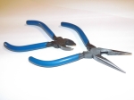
- A set of Pin-Nose Pilers and Wire Cutters

Although possible, your dentist will tell you, teeth are not suitable for stripping wires! You can probably spot most electronic engineers by the range of grove sizes between their teeth, each matching the various gauges of wire they’ve used over the years. To save your teeth, use wire strippers, there are two common types:
- Basic strippers which have various size holes to fit different size wire in.

- Basic Wire Strippers (Image: Farnell)
- Automatic trigger wire strippers, which adjust to the size of the wire and strip-it in one go.
-

Automatic Wirestrippers (Image from http://www.rapidonline.com)
- Automatic Wire Strippers (Image: Rolson Tools)
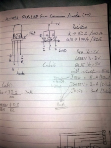
When planning a project it is really helpful to work out what you want to do and how you will do it, so a good project pad or notebook is very helpful. You will find that even notes which may feel obvious at the time, will save a lot of effort if you need to look again at a particular circuit, months or perhaps even years later. I always start with detailing the pin outs and specific features of the components I am using, which saves me having to look up the datasheet every time I use that component and is ideal for that quick sanity check before powering up.
- The now famous notepad notes (See http://www.raspberrypi.org/archives/2918).

A basic multimeter is well worth investing in (even a cheap one is useful). This will allow you to read voltages and currents from your circuit and allow you to check things before connecting anything too expensive or precious (like a Raspberry Pi)! While you only really need the most basic functions, a transistor checking function can be useful (although this can be done manually anyway) and also the continuity tester (used for checking connections) is most helpful if it beeps (mine doesn’t do that, which means you have to keep an eye on the screen).

- A basic multimeter is invaluable.

A spare biscuit/sweet tin makes an excellent box to store your collection in. A second tin for storing your components and projects in progress is also a good idea. Another useful tip is, if you buy some electrical items which come packaged with a bag of Silica Gel, then rather than throw it away, put it in the storage tin and it should help protect your tools (it will absorb moisture which will cause things to rust).
Shopping List
With just these few basic tools you can make a start with experimenting with electronics. I estimate if you are sensible about your purchases everything should cost well under £20, and if you take care of them they will last you for years (the multimeter shown I think cost me 5 euros (around £3) and is still going after 15+ years).
- Breadboard(s)
- Breadboard jumper wires, or single core wire
- Wire cutters / Hobby knife
- Wire strippers
- Notepad, Pencil and Eraser
- Storage Tin
- Multimeter
These tools become even more useful if you advance to building permanent circuits (soldering etc) which I shall cover another time.
Places to shop?
I’ve added a few links here to places which stock some of the items above, just in case you are unsure where to get them:
Adafruit: Have a selection of tools, breadboards and components (based in US)
Tandy: Stock a range of tools, breadboards and components (based in UK)
I’ve ordered things from both in the past, and I have been very happy with the value for money and service they provide.
Example Circuits
There have been several articles in the MagPi which show the use of breadboards for connecting to the Raspberry Pi’s GPIO connections.
Also Ada-Fruit’s Learning pages, have lots of tutorials and guides many of which are based on breadboards.
If you have any suggestions, require information on where to purchase items, or need more information about the tools then please leave a comment! Thanks.

[…] Guide to…Breadboarding […]