
I am proud to announce the release of my latest kit, a 5 way RGB-LED test module.
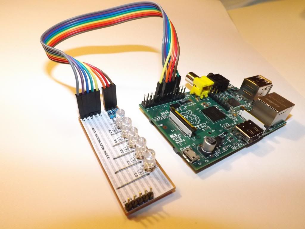
RGB LED Module connected up to Rev1 Raspberry Pi ready to go!
__________
To see more details see the main RGB-LED Kit Page
To Buy the Kit see the Shop
__________
This kit has taken me quite a while to get ready, as I’ve debated quite a bit over the design for function, flexibility, form and ease of construction. It took me a while to finally decide on what I think is the best overall solution.
I really wanted to have a clear idea of the supporting tutorial material I would provide in the user manual and on the site to support it, so I spent a lot of time experimenting with code. I’ve now planned a structured series of guides to build up the basics and introduce increasingly complex concepts. This will include several aspects of Python which personally I have found hard to find clear details about (even with looking through a number of Python books), I hope to provide these over the coming weeks.
If all goes well, I will be able to develop the lessons further into some additional guides to make and create fun projects. I would also love to see what projects people use them for and will be glad to feature any interesting projects on the site (or link to them).
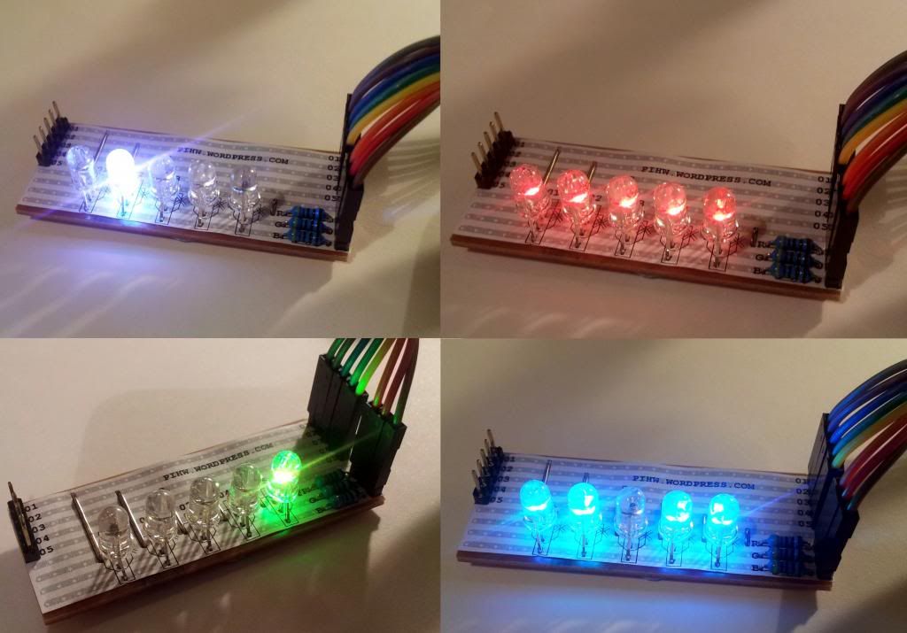
RGB LED Module in operation (Pin Header Version).
Control of the module requires 4 to 8 GPIO pins (depending on how many LEDs are being used) and it is designed to allow all 5 RGB-LEDs to be lit without excessive current draw. I have also considered as part of the design, being able to link up with some other planned modules to control multiple boards in future.
See the following link to see it in action:
Or check out the lessons in the header bar above under “My Hardware Kits”!
Finally, I’ve ensured the supplied manual (12-Pages A4 Colour) contains a similar level of detail to the PSU kit, and has everything needed to get you started:
- background details of RGB LEDs
- a detailed step by step construction guide with full-size colour photos
- the first level of the tutorials (first steps using bash and python scripts)
For more information about the principles behind these kits see my previous blog post:

[…] Introducing RGB-LED Teaching Kit […]
You did the a great work writing and revealing the hidden beneficial features of
Out of interest, what are the 5 pins on the other end of the board? I know they’re probably for linking boards together, but which GPIO pins are they?
Yes they will be for linking boards – direct link to the 01-05 pins on the other side (would just need 3 more GPIO for another board).
Could be any of the GPIO pins really, since you can wire how you like. By default, I’m using Pins 12,16,18,22 and 7 for the lessons (pin-out table is shown in lesson “0”).
Interesting question though, since you could reuse these pins by disabling the LEDs from the RGB side…
[…] Meltwater komplete prodaja za razumljivih 14.49 funtov, če pa ga ne želite kupiti, pa zadeve prav tako lahko prilagodite za svoje GPIO projekte. […]
hi ebaysays:
“Ended:20 Feb, 2013 18:13:06 GMT” am i too late? …Roland Tanglao
I’ve updated the RGB-LED page with details on how to reserve one from the next batch!
Thanks for your interest!
I got my kit yesterday. Here’s what I’ve done with it.
http://www.seanclark.me.uk/blogpost,62182.html
That is awesome!
Thanks for sharing your project and I am glad everything went so smoothly.
[…] LED kits if you want to be able to use your brand new library to play with making disco rainbows (Meltwater’s selling them for a very reasonable £14.49, and they’re a superb teaching tool) – but if you don’t have […]
Hi there, does the kit require soldering or can I just start using it straight from the box. If it does require soldering, will it be easy to do for someone who has never soldered before and is it ok to use any old soldering iron?
The kit does require soldering, but it is designed with beginners in mind. The printed user manual includes step by step instructions with clear photos of each stage. The intention is to encourage people who have not soldered before to have a go. Most standard soldering irons should be fine, although one with a fine tip will make it easier if you have one available. There is also a section on testing it before wiring to the RPi. I’ve purposely kept the need for any other tools to a minimum (wire cutters to clip the wires off when you are finished is useful, plus eye protection is generally recommended while soldering/clipping).
Feedback so far is that it is very rewarding to be able to make your own kit and then program it from scratch.
It is also available assembled, but if you are able, soldering it yourself is much much more fun (and is an excellent skill to learn).
That’s great thanks, I will have a go at soldering and hopefully don’t make a pigs ear of it!
Hello, I’m very interesting with your project. Can you send me the documentation that I can see the difficulty level of the building?
I’m not currently able to send out the documentation (although I shall put some examples on the site when I get time). However, the instructions are designed to be very detailed and easy to follow, with the 1st stage showing how to prepare the components (bending the wires etc so they fit into the template), and the 2nd stage describes placing each component with full size photos of each step (front and back). With care, most people should be able to assemble the unit.